Saf-holland XL-FW152-03 FW67 Series Air Lift Fifth wheel Manuel d'utilisateur

Naviguer en ligne ou télécharger Manuel d'utilisateur pour Pour la voiture Saf-holland XL-FW152-03 FW67 Series Air Lift Fifth wheel. SAF-HOLLAND XL-FW152-03 FW67 Series Air Lift Fifth wheel User Manual Manuel d'utilisatio

  • Télécharger
  • Ajouter à mon manuel
  • Imprimer
  • Page
    / 8
  • Table des matières
  • MARQUE LIVRES
  • Noté. / 5. Basé sur avis des utilisateurs
Vue de la page 0
XL-FW152-03
GENERAL INFORMATION:
1. Verify that you have sufficient cab-to-axle
(C.A.) clearance on the tractor for the elevating
fifth wheel (
see Figure 1). A minimum of 60˝
is required. The 60˝ C.A. dimension is the
recommended minimum and is based on a 96˝
wide square-nosed trailer with a 36˝ kingpin
setting. More or less C.A. may be required for
other nose configurations, kingpin settings,
refrigeration units, etc.
Note that the pivot centerline of the fifth wheel
top plate should be located as near as possible
to the OEM’s recommended location and a
minimum of 1˝ ahead of the suspension
centerline, when in the down position. (
see
Figure 1.)
2. The FW67 and FW69 Series lift wheels require
certain air components for operation. If these
air components are not obtained from Holland
Hitch Company, they should have the
following characteristics:
A. Air Tank – 9 cu. ft. capacity
(150 p.s.i. minimum working pr
essur
e).
B. Air Compressor Minimum 14 cu. ft.,
24 cu. ft. recommended (150 p.s.i.
minimum working pr
essur
e).
C. Hose and fittings Multipurpose hose –
medium and low pressure (see Figure 4 on
page 3, and parts list on page 5 for sizes).
C.A.
FIGURE 1
C. Mark the “T”style mounting angles for
r
equir
ed clearances. The mounting angles
may require cut outs to clear the bolts,
rivets, spring hangers, etc. on the frame.
A riser to elevate the fifth wheel assembly
and mounting angles may be required to
obtain clearance for the transmission or
crossmembers.
continued
Failure to read, understand and
follow the important information
contained herein, may result in a
hazardous condition or cause a
hazardous condition to develop.
WARNING
3. Check to see that all components and parts
are on hand.
INSTALLATION:
1. Installation of the Fifth Wheel:
A. Position the “T”style mounting angles along
the mounting base of the elevating fifth
wheel unit. Make sure the mounting angle
is flush with each end of the fifth wheel
base, then mark the fifth wheel top plate
pivot location on the mounting angle.
B. Position the mounting angles on the tractor
frame with the fifth wheel pivot location
ahead of the suspension pivot centerline
as noted above in General Information.
1˝minimum
from suspension
centerline to
fifth wheel
pivot center.
Use OEM
recommendations
Mark the fifth wheel pivot
on the mounting angle.
FIFTH
WHEELS
INSTALLATION &
MAINTENANCE
INSTRUCTIONS
FW67 & FW69 Series
Air Lift Fifth wheels
When welding, use a procedure
which assures a sound, good
quality weld and which protects
t
he operator and others.
Overwelding may cause distortion
and damage, and underwelding
may not develop sufficient strength. A low hydrogen
process and AWS E70XX filler metal are recommended.
T
ake precautions to insure that the tractor electrical
system is not damaged by the welding.
WARNING
Vue de la page 0
1 2 3 4 5 6 7 8

Résumé du contenu

Page 1 - INSTRUCTIONS

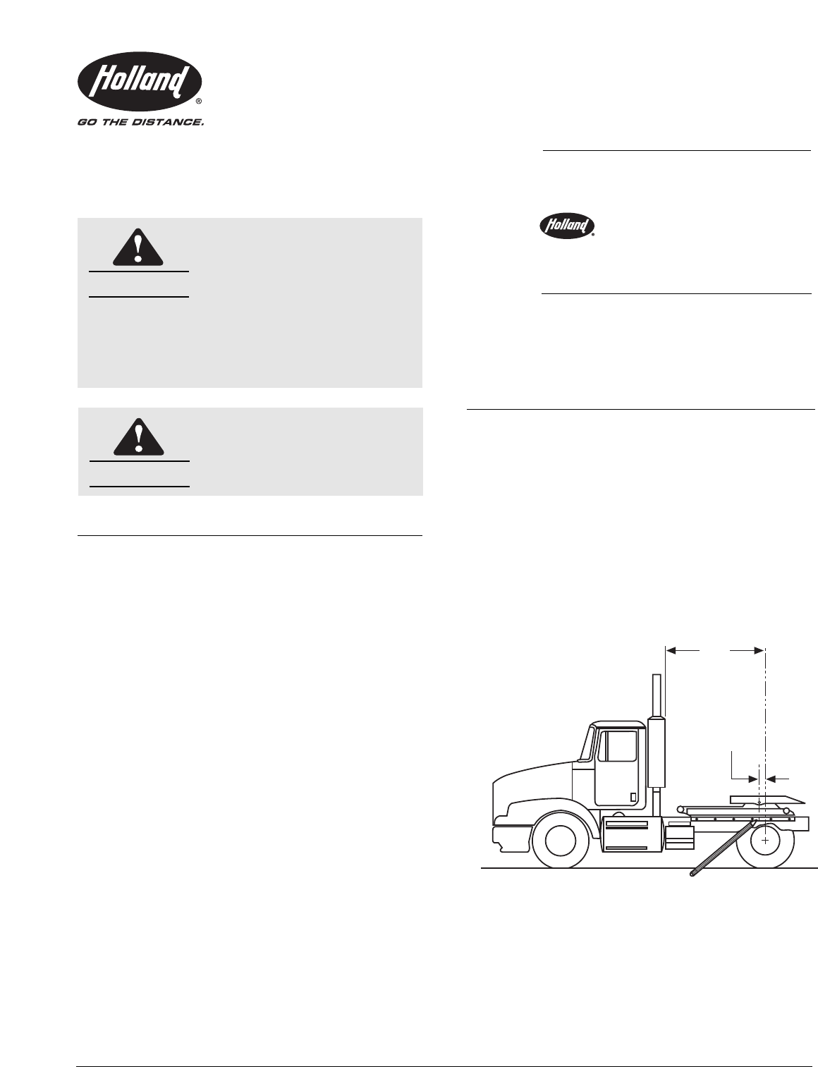
XL-FW152-03GENERAL INFORMATION:1. Verify that you have sufficient cab-to-axle(C.A.) clearance on the tractor for the elevatingfifth wheel (see Figure

Page 2 - 4. System Check:

2C. Install all air hoses and fittings as shown on the piping diagram (see Figure 4) formodel (FW67 or FW69 series) selected. Usecare to assure that a

Page 3 - FW67 and FW69 Piping Diagram

3NOTE:This line can tie into theair supply line which may beon the tractor. Consult withthe manufacturer.TRACTOR AIRSUPPLYCustomer to plug unused tank

Page 4 - FW67 and FW69 Parts Explosion

4FITTING KIT14171823191516 22 217375USE ON FW-69 SERIES ONLY707176797275747244552756395337245328563955443544524831305542416954563969494351243755443539

Page 5 - FW67 and FW69 Parts List

5ITEM PART NO. NO. PART NAME ITEM PART NO. NO. PART NAMEFW67 and FW69 Parts List1 XA-6755 2 Mtg. Angle Sub-Assy.2 XB-BR-118-C-7 2 Bolts3 XA-351-UB 1 C

Page 6 - RK-351-UB Parts Breakdown

62842211356816101014212122222671120139122315272510262417281819Accessories(not included in rebuild kit)3233Prior to 9/98Bracket Components(not included

Page 7 - Periodic Maintenance

7WEEKLY1. Apply grease to all grease fittings on the elevating assembly and fifth wheel top plate.2. Be sure the fifth wheel top plate is lubricated.3

Page 8

8Copyright © September 2002 • The Holland Group, Inc.Holland USA, Inc. Facilities:Denmark, SC Muskegon, MIDumas, AR Warrenton, MOHolland, MI Wylie, TX

Commentaires sur ces manuels

Pas de commentaire